
On March 13, 1989, a geomagnetic storm triggered by a coronal mass ejection from the Sun slammed into Earth’s magnetic field. Within 90 seconds, the entire Hydro-Quebec power grid collapsed. Six million people lost electricity for nine hours. The root cause was not equipment failure or human error. It was a phenomenon that utility engineers call geomagnetically induced currents, or GICs, flowing through power transformers and overwhelming them in ways normal AC current never could.
Understanding how geomagnetically induced currents damage power transformers has become one of the most pressing concerns in grid reliability. As we move deeper into Solar Cycle 25 and approach the next solar maximum, the risk of severe geomagnetic disturbances is rising. Utilities, regulators, and grid operators worldwide are paying closer attention to space weather than ever before.
In this guide, we break down exactly what GICs are, how they travel from the Sun to your local substation, and the specific mechanisms by which they destroy multi-million-dollar transformers. Whether you are a power systems engineer, a grid operator, or simply someone fascinated by space weather, you will find a clear, technically accurate explanation here.
We have drawn on data from the 1989 Hydro-Quebec blackout, the 2003 Halloween storms, and the May 2024 solar storm sequence to ground every explanation in real-world evidence. We also cover the regulatory framework, including NERC TPL-007 and FERC Order 830, that now governs how utilities must assess and mitigate GIC risk.
Our team spent weeks reviewing IEEE research papers, NERC standards documentation, and vendor white papers from organizations like SEL, Hitachi Energy, and ABB to build this resource. We also looked at forum discussions from working linemen and grid operators who have experienced geomagnetic disturbances firsthand. Their real-world perspective adds a layer of practical knowledge that pure academic sources often miss.
Table of Contents
Quick Answer: How Do Geomagnetically Induced Currents Damage Power Transformers?
Geomagnetically induced currents damage power transformers by driving quasi-DC current through transformer windings during geomagnetic storms. This DC current forces the transformer core into half-cycle saturation, which causes massive increases in magnetizing current, stray flux heating in the tank and structural parts, harmonic generation that disrupts protective relays, and reactive power absorption that destabilizes grid voltage. Prolonged saturation leads to thermal damage, insulation breakdown, and potentially permanent transformer failure.
What Are Geomagnetically Induced Currents (GICs)?
Geomagnetically induced currents (GICs) are quasi-direct electrical currents that flow through grounded conductive systems on Earth’s surface during geomagnetic storms. In power grids, they enter through transformer neutral connections and ride along high-voltage transmission lines. Unlike the 50 Hz or 60 Hz alternating current that normally flows through the grid, GICs change slowly over minutes or hours, behaving like a DC offset superimposed on AC power.
The story of GICs begins 93 million miles away, on the Sun. During periods of high solar activity, the Sun releases enormous bubbles of plasma and magnetic field called coronal mass ejections (CMEs). A single CME can carry billions of tons of charged particles at speeds exceeding 2,000 kilometers per second. When a CME is directed at Earth, it arrives within one to three days.
When this solar plasma reaches Earth, it interacts with the magnetosphere, the protective magnetic bubble surrounding our planet. The collision compresses the magnetosphere and sends shockwaves through the geomagnetic field. These rapid changes in the magnetic field induce electric fields at Earth’s surface through Faraday’s law of induction. A changing magnetic field creates an electric field, and that electric field drives current through anything conductive in the ground.
These currents are sometimes called telluric currents, a term that predates the modern understanding of space weather. The concept dates back to 1847, when telegraph operators noticed that their equipment could operate without battery power during auroral displays. The telegraph lines were picking up telluric currents generated by the same geomagnetic disturbances that produced the visible aurora.
The magnitude of GICs depends on several factors. The strength of the geomagnetic storm, the electrical conductivity of the underlying Earth (which varies by geology), and the orientation and length of the transmission lines all matter. GIC amplitudes typically range from tens to hundreds of amperes in large power transformers. During extreme storms, currents can exceed 200 amperes in individual transformers.
It is worth noting that not every geomagnetic storm produces significant GICs. The orientation of the interplanetary magnetic field (IMF) carried by the solar wind matters enormously. A southward-directed IMF component couples most efficiently with Earth’s magnetic field, producing the strongest disturbances and the largest GICs. This is why two CMEs of similar size can produce wildly different impacts on power grids.
GICs are not limited to power grids. They also affect buried pipelines, railway signaling systems, and undersea telecommunications cables. But the power grid is where GICs cause the most economically significant damage, because of the critical role transformers play and their extreme cost and replacement difficulty.
The Solar Wind and Geomagnetic Storm Connection
The Sun operates on an approximately 11-year cycle of activity known as the solar cycle. During solar maximum, sunspot numbers peak, and the Sun produces more frequent and intense solar flares and coronal mass ejections. The current cycle, Solar Cycle 25, began in late 2019 and is expected to reach its peak between 2024 and 2026.
A geomagnetic storm occurs when a CME or a high-speed solar wind stream from a coronal hole arrives at Earth and couples effectively with the magnetosphere. The storm intensity is measured using the disturbance storm time (Dst) index and the Kp index. A Kp of 5 or higher indicates a geomagnetic storm capable of producing significant GICs. The March 1989 storm reached a Kp of 9, the maximum value on the scale.
The auroral electrojet, a massive ring of current flowing in the ionosphere at altitudes of 100 to 300 kilometers, is the immediate driver of GICs. During geomagnetic storms, the electrojet intensifies and shifts equatorward. The changing current in the electrojet produces the magnetic field fluctuations that induce the surface electric fields responsible for GICs. Regions directly beneath the electrojet experience the strongest GICs.
Understanding this chain, from solar activity to electrojet intensification to surface electric fields to GIC flow, is the foundation for everything that follows. The transformer damage mechanism builds on this physical pathway.
How GICs Enter Power Grids and Reach Transformers
Understanding how geomagnetically induced currents damage power transformers requires knowing the path these currents take from the ground into the grid. GICs do not enter through the same path as normal AC power. They exploit the grounding system that exists for safety reasons.
High-voltage transmission lines stretch across hundreds of miles, acting as enormous antennas. The surface electric field induced by the geomagnetic storm drives current along these lines. But the current needs a return path, and it finds one through the grounded neutrals of power transformers.
The Role of Grounded Wye-Connected Transformers
Most large power transformers at transmission substations use a wye (Y) connection on the high-voltage side, with the neutral point solidly grounded. This grounding is essential for normal AC operation. It provides a path for fault currents, stabilizes system voltage, and protects equipment from lightning strikes and other surges.
However, this same ground connection becomes the entry point for GICs. The quasi-DC current induced in the ground by the geomagnetic storm flows up through the transformer neutral, through the winding, out onto the transmission line, and eventually returns through another transformer’s neutral elsewhere on the grid. The result is a DC current loop that passes through transformer windings.
Delta-connected transformers, by contrast, have no accessible neutral point. Current cannot flow into or out of a delta winding through a ground connection. This makes delta-connected transformers largely immune to direct GIC flow, though they can still be affected by the grid-level effects of GICs on neighboring transformers. Many utilities exploit this difference by specifying delta connections on the high-voltage side where system conditions permit, reducing GIC exposure.
The distinction between wye and delta connections is one of the most important factors in GIC vulnerability. A substation with all wye-grounded transformers presents multiple GIC entry and exit points. A substation with delta-connected transformers effectively blocks DC current flow through those transformers. System planners use this knowledge when designing new substations in high-risk areas.
Why Grid Topology Matters for GIC Risk
The susceptibility of a power grid to GICs depends heavily on its physical layout and location. Three key factors determine GIC risk for any given grid segment.
First, geomagnetic latitude plays a major role. Grids at higher latitudes are closer to the auroral electrojet, the intense current system in the ionosphere that drives GIC production. This is why Canada, Scandinavia, and the northern United States face higher GIC risk than grids near the equator. During severe storms, the auroral zone expands equatorward, pushing GIC risk into regions that rarely experience it. During the May 2024 storms, GIC effects were measured as far south as Texas and Florida.
Second, transmission line length matters. Longer lines intercept more of the surface electric field, generating larger GICs. A 500-mile transmission line will see much higher induced currents than a 50-mile line under the same geomagnetic conditions. This is why long-distance transmission corridors, such as those connecting remote generation to load centers, are particularly vulnerable. The Hydro-Quebec James Bay corridor, stretching over 1,000 kilometers, is a textbook example.
Third, Earth conductivity determines how efficiently the induced electric field drives current. Regions with resistive bedrock near the surface (such as the Canadian Shield or much of Scandinavia) experience stronger surface electric fields and therefore higher GICs. Regions with conductive sedimentary layers see weaker fields at the surface because the currents preferentially flow through the deeper conductive layers rather than along the surface.
The interaction of these three factors means that GIC risk varies dramatically even within a single utility’s territory. A substation in northern Minnesota on a long transmission corridor over resistive bedrock faces far higher GIC risk than a downtown substation on a short feeder over conductive soil. This variability is why GIC assessments must be performed on a substation-by-substation basis.
The GIC Damage Pathway: Step by Step
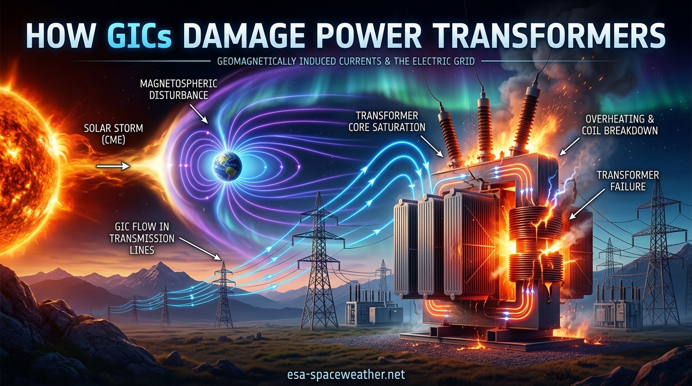
The path from solar storm to transformer damage follows a clear, predictable sequence. Understanding each step helps clarify why the damage happens and why it can occur so quickly:
Step 1: A coronal mass ejection erupts from the Sun and travels toward Earth at 400 to 2,000 km/s. Solar observatories like SOHO and STEREO detect the eruption, giving Earth-based operators one to three days of advance notice.
Step 2: The CME arrives at Earth and compresses the magnetosphere, causing rapid fluctuations in the geomagnetic field. The Dst index drops sharply, indicating the onset of a geomagnetic storm.
Step 3: The changing magnetic field induces a surface electric field across the ground, typically measured in volts per kilometer. During severe storms, surface electric fields of 5 to 20 V/km can develop.
Step 4: The electric field drives quasi-DC current along transmission lines and through the grounded neutrals of wye-connected transformers. GIC magnitudes depend on line length and orientation relative to the electric field.
Step 5: The DC current entering the transformer winding creates a DC offset in the core’s magnetic flux, pushing it into half-cycle saturation. Even modest DC current levels (15 to 25 amperes per phase) can trigger deep saturation in a large transformer.
Step 6: Half-cycle saturation triggers a cascade of damaging effects, including massive magnetizing current spikes, stray flux heating, harmonic generation, and reactive power absorption.
Step 7: Depending on the severity and duration of the GIC event, the transformer experiences anything from temporary performance degradation to irreversible thermal damage and complete failure.
This entire chain can unfold in minutes. The Hydro-Quebec grid collapsed just 90 seconds after the GIC surge began. Grid operators often have very little time to react, which makes prediction and advance warning so critical to protecting infrastructure.
Which Transformers Are Most Vulnerable to GICs?
Not all transformers face the same level of GIC risk. Several design and installation factors determine vulnerability, and understanding these differences helps utilities prioritize their mitigation investments.
Large, high-voltage transformers (200 kV and above) are the primary targets. These transformers have grounded wye connections, operate with core flux densities close to the saturation knee point, and serve as the interconnection points between transmission systems. Their size means that even moderate GIC levels can push the core deep into saturation.
Transformers with three-limb, three-phase core designs are somewhat less susceptible than five-limb or single-phase designs. In a three-limb core, the zero-sequence flux path has higher reluctance because it must return through the air and tank rather than through additional core limbs. This naturally limits the saturation effect of GICs. Five-limb cores provide an easier magnetic return path, making them more vulnerable to saturation from DC bias. This design difference is one reason utilities in high-GIC-risk regions sometimes prefer three-limb core construction.
Autotransformers, which are common at transmission voltage levels, are particularly susceptible because their design includes a grounded neutral that provides a direct path for GICs. The series and common windings of an autotransformer both carry GIC, compounding the saturation effect. Since autotransformers are widely used for interconnections between voltage levels, they represent a significant portion of the GIC-vulnerable transformer population.
Older transformers with degraded insulation are at greater risk of permanent damage. A transformer that has operated for 30 or 40 years may have paper insulation that is already near its thermal limits. The additional heating from a GIC event can push the insulation past the point of failure, causing a short circuit between windings. This is particularly concerning because the aging transformer fleet in North America and Europe includes many units installed in the 1960s and 1970s.
Phase-shifting transformers and voltage-regulating transformers also deserve attention. These specialized units often have complex winding arrangements that can make them more sensitive to DC bias. Utilities should include all transformer types above the 200 kV threshold in their GIC vulnerability assessments, not just standard power transformers.
How GICs Damage Power Transformers: The Physics of Half-Cycle Saturation
The central mechanism by which geomagnetically induced currents damage power transformers is a phenomenon called half-cycle saturation. Understanding this process is the key to understanding every downstream effect, from heating to harmonics to voltage collapse. If you take away one concept from this entire article, make it this one.
Normal Transformer Operation
Under normal conditions, a power transformer operates with an alternating magnetic flux in its iron core. The flux swings symmetrically between positive and negative values at the system frequency (50 or 60 Hz). The transformer is designed so that the peak flux stays below the saturation knee of the core steel’s magnetization curve. In this linear region, the magnetizing current required to produce the flux is small, typically just 1 to 3 percent of the rated current.
Think of the core as a sponge. In normal operation, the sponge absorbs and releases magnetic flux with each AC cycle, never getting fully saturated. The small amount of magnetizing current is like gently squeezing the sponge, just enough to move the flux back and forth without overfilling it.
The saturation knee is the point on the magnetization curve where the core steel can no longer absorb additional magnetic flux efficiently. Below the knee, flux increases linearly with magnetizing force. Above the knee, enormous increases in magnetizing force produce only small increases in flux. The core is essentially full.
What Happens When DC Current Enters the Winding
When a quasi-DC current from a GIC event enters the transformer winding, it creates a constant magnetic flux offset in the core. This DC flux adds to the normal AC flux during one half of the cycle and subtracts during the other half. The result is that the core now operates asymmetrically rather than symmetrically.
During the half-cycle where the DC and AC flux add together, the total flux pushes past the saturation knee. The core enters deep saturation. During the opposite half-cycle, the DC flux subtracts from the AC flux, keeping the core well below saturation. This is why the phenomenon is called half-cycle saturation. The core saturates on one half of the AC cycle and remains unsaturated on the other.
The amount of DC flux depends on the magnitude of the GIC and the transformer’s core geometry. Even a small DC current, measured in amperes, can produce a significant flux bias because the transformer core is designed to operate near the saturation knee for efficiency. There is very little margin between normal operating flux and saturation flux in a well-designed transformer.
The Consequences of Half-Cycle Saturation
Once the core saturates during one half-cycle, the permeability of the iron drops dramatically. The core can no longer efficiently guide magnetic flux. To maintain the same voltage in the winding (which is fixed by the system), the transformer must draw enormously more magnetizing current during the saturated half-cycle.
Returning to the sponge analogy: half-cycle saturation is like pushing the sponge past its capacity on every other squeeze. The excess water has nowhere to go, so it spills out chaotically. In a transformer, this spilled magnetic energy manifests as stray flux, excessive current draw, and distorted waveforms.
The magnetizing current, normally just 1 to 3 percent of rated current, can spike to 10, 20, or even 50 times its normal value during the saturated half-cycle. This current is highly distorted and rich in harmonics. It pulses through the windings once per cycle, generating heat and mechanical stress on the winding conductors and supports.
Even a relatively small DC current can trigger severe half-cycle saturation. Research has shown that a GIC of just 15 to 25 amperes per phase can drive a typical 500 kV transformer into deep saturation. During extreme storms, GICs of 100 to 200 amperes have been measured, far exceeding the threshold for saturation and creating extreme stress on the transformer.
The relationship between GIC magnitude and saturation depth is nonlinear. Once the core passes the saturation knee, each additional ampere of GIC produces progressively larger increases in magnetizing current. This nonlinear response means that a doubling of GIC from 25 to 50 amperes can produce far more than a doubling of the damaging effects.
Why Half-Cycle Saturation Is So Destructive
Half-cycle saturation is uniquely destructive because it simultaneously creates multiple failure modes within the transformer. The massive magnetizing current pulses heat the windings. The stray flux from the saturated core induces eddy currents in the tank walls and structural steel. The harmonic-rich current disrupts the entire power system.
These effects compound each other. Heating increases resistance, which changes the current distribution within the windings. Harmonics interfere with the AC waveform, potentially tripping protective relays that disconnect healthy equipment. Reactive power demand spikes, pulling grid voltage down and potentially causing voltage collapse that affects the entire transmission network.
The damage can happen quickly. Under severe saturation, hotspot temperatures in the transformer tank and structural parts can reach dangerous levels within minutes. The 2003 Halloween storms caused a transformer at a South African utility to fail catastrophically after sustained GIC exposure. Post-mortem analysis revealed severe thermal damage consistent with half-cycle saturation effects.
What makes half-cycle saturation particularly insidious is that it can be invisible to normal monitoring. A transformer can be in deep saturation with massive internal heating, yet show only modest changes in its external electrical measurements until damage has already occurred. Load current may look normal while the magnetizing current, which is not typically monitored on older transformers, is spiking to destructive levels. This is why specialized GIC monitoring systems have become essential for high-risk substations.
Types of Transformer Damage Caused by GICs
Half-cycle saturation sets off a chain reaction that produces several distinct types of damage. Understanding each one helps explain why GIC events are so dangerous and why they can cause such varied failure modes across different transformer designs.
Thermal Damage to Windings and Structural Parts
The most immediate effect of half-cycle saturation is heat. The massive magnetizing current pulses that accompany saturation flow through the transformer windings, generating copper losses (I squared R losses). Since the current can be 10 to 50 times normal during the saturated half-cycle, the heating effect is enormous and concentrated in the winding conductors.
But the windings are not the only part that heats up. When the core saturates, magnetic flux that would normally be contained within the core steel spills outward into the transformer tank and structural components. This stray flux induces eddy currents in the steel tank walls, core clamps, tie plates, and other metallic parts. These eddy currents create localized hotspots that can reach temperatures sufficient to damage insulation and, in extreme cases, melt metal.
Studies have shown that hotspot temperatures in the tank wall can exceed 150 degrees Celsius during severe GIC events. At these temperatures, the paper insulation on nearby windings degrades rapidly. Oil temperatures also rise, reducing its dielectric strength and accelerating the aging of all internal components. In the worst cases, oil can begin to break down chemically, producing gases that indicate internal faults.
The Effect of GIC on Transformer Tank Loss
One of the most frequently asked questions about GIC damage relates specifically to tank loss, and it deserves a thorough answer. When a transformer core enters half-cycle saturation, the increased stray flux that escapes the core enters the transformer tank. This flux induces circulating currents in the tank walls, creating what engineers call tank loss or stray load loss.
Under normal operation, tank loss is a small fraction of the transformer’s total losses, typically less than 10 percent. During half-cycle saturation, tank loss can increase by a factor of 10 or more. This additional loss manifests as heat in the tank walls, contributing to the thermal stress on the entire transformer system. The elevated tank loss directly degrades insulation by raising the operating temperature beyond design limits.
The relationship between stray flux and tank loss is well documented in transformer engineering literature. Hitachi Energy (formerly ABB) has published detailed studies showing that GIC-driven saturation can push tank loss to levels that exceed the thermal design limits of the transformer. This is one of the primary reasons why utilities must take GIC risk seriously. Tank loss is not just an efficiency concern. It is a direct pathway to equipment destruction.
Harmonic Generation and Protective Relay Misoperation
The distorted magnetizing current caused by half-cycle saturation is rich in harmonics, particularly the second, third, fourth, and fifth harmonics. These harmonic currents do not stay confined to the saturated transformer. They propagate throughout the power system, causing a range of problems that can be just as damaging as the heating effects.
Second harmonic currents can interfere with transformer differential protection schemes. Differential relays use the second harmonic content of the inrush current to distinguish between legitimate transformer energization (inrush) and internal faults. When a transformer in saturation generates large amounts of second harmonic current during normal operation, the relay may block tripping when it should operate, or it may trip falsely, disconnecting a healthy transformer from the grid. Either scenario is dangerous for system reliability.
Third harmonic currents can cause overheating in neutral conductors and grounded wye-connected equipment. They also interfere with capacitor banks and harmonic filters, potentially tripping these devices off-line when they are needed most for voltage support. When capacitor banks trip due to harmonic overload, the grid loses reactive power resources at the exact moment when saturated transformers are consuming extra reactive power. This double effect accelerates voltage decline.
Fifth harmonic currents create negative-sequence components that can cause overheating in motors and generators connected to the grid. The cumulative effect of these harmonics across the system can trigger a cascade of protection operations that disconnect large amounts of equipment, accelerating a potential blackout even when the underlying equipment is physically undamaged.
Reactive Power Absorption and Voltage Instability
Perhaps the most grid-threatening consequence of half-cycle saturation is massive reactive power absorption. When a transformer draws enormous magnetizing current, it consumes large amounts of reactive power (measured in volt-amperes reactive, or VARs). A single saturated transformer can absorb hundreds of megavars of reactive power from the grid.
Reactive power is what maintains voltage levels across the transmission system. Without sufficient reactive power support, voltage sags, and if it sags far enough, the system becomes unstable. When multiple transformers simultaneously absorb reactive power during a GIC event, grid voltage begins to drop rapidly.
If the voltage drops far enough, other equipment such as capacitor banks and static VAR compensators may trip off-line due to undervoltage protection. This further reduces reactive power support, causing a cascading voltage collapse that can bring down an entire interconnection in seconds.
This is exactly what happened during the 1989 Hydro-Quebec blackout. Multiple large transformers simultaneously absorbed reactive power during the geomagnetic storm, collapsing grid voltage within seconds. Seven Static VAR Compensators tripped in rapid succession as their protective systems detected undervoltage conditions. With reactive power support gone, the entire grid collapsed before operators could respond. The entire sequence, from the start of the GIC surge to complete grid collapse, took approximately 90 seconds.
Insulation Degradation and Long-Term Damage
Even when a transformer survives a GIC event without immediate failure, the thermal and electrical stress can cause cumulative insulation damage that shortens the transformer’s useful life. Transformer insulation is primarily cellulose-based paper and pressboard immersed in mineral oil. Each thermal event accelerates the aging of these materials, and the aging is permanent and irreversible.
The Arrhenius equation governs insulation aging. For approximately every 6 to 8 degrees Celsius increase in operating temperature, the rate of insulation aging doubles. A GIC event that raises hotspot temperatures by 30 degrees Celsius above normal for even an hour can age the insulation by the equivalent of several months of normal operation. Repeated GIC exposures compound this effect, shortening transformer life and increasing the probability of future failures during routine operating conditions.
In some cases, the damage is immediate and detectable. GIC-induced hotspots can cause gas bubbles in the transformer oil, which the dissolved gas analysis (DGA) can detect after the event. The presence of acetylene gas, in particular, indicates arcing or severe overheating inside the transformer. Ethylene and methane gases indicate lower-temperature thermal faults. Utilities routinely perform DGA after significant geomagnetic storms to check for latent damage that may not have triggered alarms during the event itself.
This cumulative damage effect means that a transformer does not need to fail during a GIC event to be damaged by it. A series of moderate storms over several years can progressively degrade insulation to the point where the transformer fails months or years later, during what appears to be normal operating conditions. The connection to the original GIC exposure is not always obvious, which makes tracking and documentation of GIC events essential for long-term asset management.
Historical GIC Damage Events: When Solar Storms Hit the Grid
The theoretical understanding of GIC transformer damage is sobering, but the real-world evidence is even more compelling. Over the past 170 years, several major space weather events have demonstrated the destructive potential of geomagnetically induced currents. These events provide the empirical foundation for everything we know about GIC damage.
The Carrington Event (1859)
The Carrington Event of September 1859 remains the most powerful geomagnetic storm in recorded history. Named after British astronomer Richard Carrington, who observed the associated solar flare, the storm produced auroras visible as far south as Cuba and Hawaii. Telegraph systems worldwide malfunctioned, with some operators receiving electric shocks and telegraph paper spontaneously igniting from the induced currents.
No power grid existed in 1859, so we have no direct evidence of transformer damage from this event. However, studies by the National Academy of Sciences estimate that a Carrington-level event today could cause widespread transformer damage across North America and Europe. The economic impact could exceed one trillion dollars, with recovery taking months to years as damaged transformers are replaced at manufacturing facilities that have limited production capacity.
The Hydro-Quebec Blackout (March 1989)
The March 1989 geomagnetic storm remains the most significant documented case of GIC damage to a modern power grid. On March 13, a severe geomagnetic storm drove GICs through the Hydro-Quebec transmission system. The James Bay transmission network, which carries power from northern Quebec to population centers in the south, was particularly vulnerable due to its high latitude and the resistive Canadian Shield geology beneath it.
Within seconds, GIC-induced saturation caused massive reactive power absorption across multiple transformers. Every Static VAR Compensator on the network tripped. Grid voltage collapsed, and protective systems disconnected the entire network in cascading fashion. Six million customers lost power for nine hours.
While no transformers were permanently destroyed in this event, the grid was brought to the absolute brink. Several transformers experienced significant thermal stress, and post-event inspections revealed evidence of insulation distress. The Hydro-Quebec blackout was the wake-up call that transformed GIC awareness from an academic curiosity into a recognized operational threat to power system reliability.
The Halloween Storms (October-November 2003)
The Halloween storms of 2003 produced some of the clearest evidence of actual transformer destruction by GICs. During this intense period of solar activity, power grids in both the Northern and Southern Hemispheres experienced significant GIC impacts.
In South Africa, a large power transformer at the Matimba power station failed catastrophically during the storm. The transformer had been in good operating condition before the event, with no indication of impending failure. Post-mortem analysis by Eskom, the South African utility, revealed thermal damage patterns consistent with GIC-induced half-cycle saturation. This case is frequently cited in IEEE literature as direct evidence that GICs can destroy transformers, even at relatively low geomagnetic latitudes.
In Sweden, the same storm sequence caused voltage collapse and brief power outages affecting approximately 50,000 customers. GIC monitoring systems recorded currents exceeding 100 amperes in some transformers. In the United Kingdom, the National Grid reported GIC-driven disturbances and increased reactive power demand on its transmission system.
The May 2024 Solar Storms
The May 2024 geomagnetic storms, triggered by a large active sunspot region (AR3664), produced some of the strongest GIC conditions since 2003. Auroras were visible across all 50 U.S. states and as far south as Mexico and northern Africa. Grid operators worldwide activated GMD operating procedures and reported system alarms and reactive power excursions across multiple control areas.
While no catastrophic transformer failures were publicly reported from the May 2024 event, multiple utilities confirmed GIC-induced alarms and voltage disturbances. Several utilities reported that their GIC monitoring systems captured significant neutral currents during the peak of the storm. The event validated the importance of advance warning systems and GIC monitoring infrastructure that has been deployed since the 2003 storms.
The May 2024 event also demonstrated something important: even moderate geomagnetic storms can stress grid operations, even when no permanent damage occurs. The accumulation of minor thermal stress from repeated events over the solar cycle may contribute to long-term insulation degradation in ways that are difficult to track. This reinforces the need for post-event dissolved gas analysis and long-term asset health monitoring.
What a Future Extreme Event Could Do
The forum discussions among linemen and grid operators reveal a sobering concern that warrants open discussion. A Carrington-level event striking today could simultaneously damage dozens or hundreds of large power transformers across a continent. With replacement lead times of 12 to 24 months for large power transformers and global manufacturing capacity limited to a few hundred units per year, recovery from such an event could take years.
Grid operators have acknowledged that GIC risk assessment is now a standard part of grid planning, but mitigation implementation remains uneven across the industry. Some utilities have invested heavily in GIC monitoring, blocking devices, and hardened transformer designs. Others have completed only the minimum regulatory requirements. The gap between best practices and minimum compliance represents a systemic vulnerability that the industry continues to address.
Protection, Standards, and Mitigation Strategies
Following the 1989 Hydro-Quebec blackout and subsequent GIC events, the electric utility industry and regulators have developed a framework for protecting power transformers from geomagnetically induced current damage. This framework combines mandatory standards, monitoring technology, operational procedures, and hardware mitigation approaches.
NERC TPL-007: The Mandatory GIC Standard
In the United States, the North American Electric Reliability Corporation (NERC) developed TPL-007, a mandatory reliability standard that requires utilities to assess the vulnerability of their bulk electric systems to geomagnetic disturbances. The standard was approved by the Federal Energy Regulatory Commission (FERC) through FERC Order 830, making compliance legally enforceable for all bulk power system owners and operators.
Under TPL-007, utilities must conduct GIC vulnerability assessments using specified benchmark geomagnetic disturbance events. The standard defines a 1-in-100-year benchmark storm and requires utilities to evaluate whether their transformers would survive the resulting GIC levels. If the assessment shows that any transformer would be damaged under the benchmark scenario, the utility must implement mitigation measures. These measures can include operational procedures, equipment modifications, or installation of GIC blocking devices.
The standard applies to transformers rated 200 kV and above, reflecting the understanding that these large units are the most vulnerable to GIC damage. Utilities must periodically update their assessments as grid topology changes and as new transformer vulnerability data becomes available from manufacturers and research institutions.
GIC Monitoring Systems
Real-time GIC monitoring has become an essential tool for grid operators in high-risk regions. Specialized GIC sensors measure the DC current flowing in transformer neutrals, providing operators with visibility into GIC conditions as they develop in real time. These monitoring systems are typically integrated with SCADA (Supervisory Control and Data Acquisition) systems to provide centralized visibility across the entire transmission network.
Modern GIC monitors can detect currents as small as a fraction of an ampere, well below the threshold for transformer damage. This early detection gives operators time to implement protective measures, such as reducing loading on vulnerable transformers, bringing additional reactive power resources online, or reconfiguring the transmission network to limit GIC flow paths.
Companies like Dynamic Ratings, SEL, and ABB manufacture GIC monitoring equipment specifically designed for utility substations. These systems range from simple neutral current sensors to comprehensive transformer monitoring platforms that track GIC alongside thermal, dissolved gas, and partial discharge data for complete asset health visibility.
Space Weather Forecasting and Operational Procedures
The ability to forecast geomagnetic storms before they arrive has improved significantly over the past two decades. NOAA’s Space Weather Prediction Center provides real-time alerts and forecasts that grid operators use to implement GMD operating procedures. These procedures typically begin when a coronal mass ejection is detected on the Sun, giving operators one to three days of advance notice before the storm reaches Earth.
When a geomagnetic storm warning is issued, utilities may take several preventive actions. They can reduce loading on vulnerable transformers to provide thermal margin. They can cancel planned maintenance outages to keep redundant equipment available. They can adjust protective relay settings to prevent false trips from harmonic currents. And they can pre-position repair crews and spare equipment in anticipation of potential damage.
The limitation, as forum discussions among utility professionals highlight, is prediction accuracy. Grid operators note that we are still not highly skilled at predicting the severity of GMD events. A CME that looks dangerous may produce only a minor storm if the IMF orientation is unfavorable for coupling with Earth’s magnetic field. Conversely, a seemingly modest event can cause significant impacts if the IMF aligns southward when it arrives. This uncertainty means that operators must treat every significant CME detection seriously, even when most events ultimately prove benign.
Hardware Mitigation Approaches
Several hardware-based approaches exist for protecting transformers from GIC damage, each with different cost, complexity, and effectiveness profiles that utilities must weigh carefully.
Neutral blocking devices install capacitors in the transformer neutral connection. Since capacitors block DC current while passing AC current, these devices effectively prevent GICs from entering the transformer winding through the neutral. However, they require careful engineering to ensure they do not interfere with normal system protection, fault current return paths, or introduce resonance problems that could damage other equipment.
Series capacitors on transmission lines can also reduce GIC flow by blocking the quasi-DC path along the line. Many high-voltage transmission systems already use series capacitors for AC power flow control, but they may need additional design considerations to handle GIC-related duty and ensure that their bypass protection operates correctly under geomagnetic disturbance conditions.
Transformers can be specified with higher GIC tolerance at the design and manufacturing stage. Manufacturers can design cores with higher saturation margins, three-limb core configurations for three-phase units, or flux shunts that limit stray flux entering the tank. These design modifications add cost but may be justified for transformers in high-risk locations or for critical grid interconnections where failure would have outsized consequences.
Despite these options, no single mitigation approach is universally adopted across the industry. Most utilities rely on a combination of monitoring, operational procedures, and selective hardware deployment, prioritizing the highest-risk transformers based on their GIC vulnerability assessments and the cost-benefit analysis of each mitigation option.
FAQs
What are geomagnetic induced currents in power transformers?
Geomagnetically induced currents (GICs) are quasi-direct currents that flow through power transformers during geomagnetic storms. When a coronal mass ejection from the Sun disturbs Earth’s magnetic field, it induces electric fields at the ground that drive currents through transmission lines and into the grounded neutral windings of transformers, forcing the transformer core into half-cycle saturation.
What is the effect of geomagnetically induced current on the loss of transformer tank?
GIC causes half-cycle saturation of the transformer core, which forces excess magnetic flux out of the core and into the transformer tank. This stray flux induces circulating eddy currents in the tank walls, significantly increasing tank loss. The additional heating from elevated tank loss can raise hotspot temperatures beyond the design limits of the transformer’s insulation system, accelerating thermal degradation.
Why do utilities respect geomagnetically induced currents?
Utilities respect GICs because they have caused real blackouts, most notably the 1989 Hydro-Quebec collapse that left six million people without power for nine hours. A severe geomagnetic storm can simultaneously damage multiple large transformers across a wide region. With replacement lead times of 12 to 24 months and costs of millions of dollars per unit, the economic and reliability risks are too large to ignore. Regulatory standards like NERC TPL-007 now require formal GIC vulnerability assessments.
What are geomagnetically induced currents?
Geomagnetically induced currents (GICs) are electrical currents induced at Earth’s surface by rapid changes in the geomagnetic field caused by space weather events such as geomagnetic storms. These currents flow through any conducting structure grounded in the Earth, including power transmission grids and pipelines, with magnitudes ranging from tens to hundreds of amperes during moderate to severe storms.
Can geomagnetic storms permanently destroy power transformers?
Yes, geomagnetic storms can permanently destroy power transformers. The most documented case occurred during the 2003 Halloween storms, when a large transformer at the Matimba power station in South Africa failed catastrophically. Post-mortem analysis confirmed thermal damage patterns consistent with GIC-induced half-cycle saturation. The risk depends on the storm severity, transformer design, and duration of GIC exposure.
How much GIC current does it take to damage a transformer?
Research shows that a GIC of just 15 to 25 amperes per phase can drive a typical 500 kV power transformer into deep half-cycle saturation. The exact damage threshold depends on the transformer design, core type, and operating conditions. During extreme storms, GICs exceeding 100 to 200 amperes have been measured in individual transformers, far exceeding the saturation threshold and creating severe risk of thermal damage.
Conclusion: The Growing Importance of GIC Awareness
Understanding how geomagnetically induced currents damage power transformers is no longer an academic exercise. It is an operational necessity for every utility operating at transmission voltage levels. The physics of half-cycle saturation is well understood, the historical evidence from 1989 and 2003 is compelling, and the regulatory framework under NERC TPL-007 now demands formal action from every bulk power system owner and operator.
The good news is that the industry has made real progress since the Hydro-Quebec blackout. GIC monitoring systems are deployed at critical substations across North America and Europe. Space weather forecasting from NOAA provides advance warning that gives operators time to prepare. Operational procedures give grid operators a clear playbook for responding to storm warnings. And mandatory reliability standards ensure that utilities cannot ignore the risk.
The challenge ahead is closing the gap between what we know and what we have implemented. Not every vulnerable transformer is monitored. Not every utility has completed its TPL-007 mitigation. And as the May 2024 storms reminded us, nature does not wait for us to be ready. The question is not whether the next major geomagnetic storm will come, but whether our transformers will be prepared when it does. For anyone involved in power system planning, operations, or asset management, understanding GIC damage mechanisms is the essential first step toward ensuring grid resilience in an active solar cycle.