
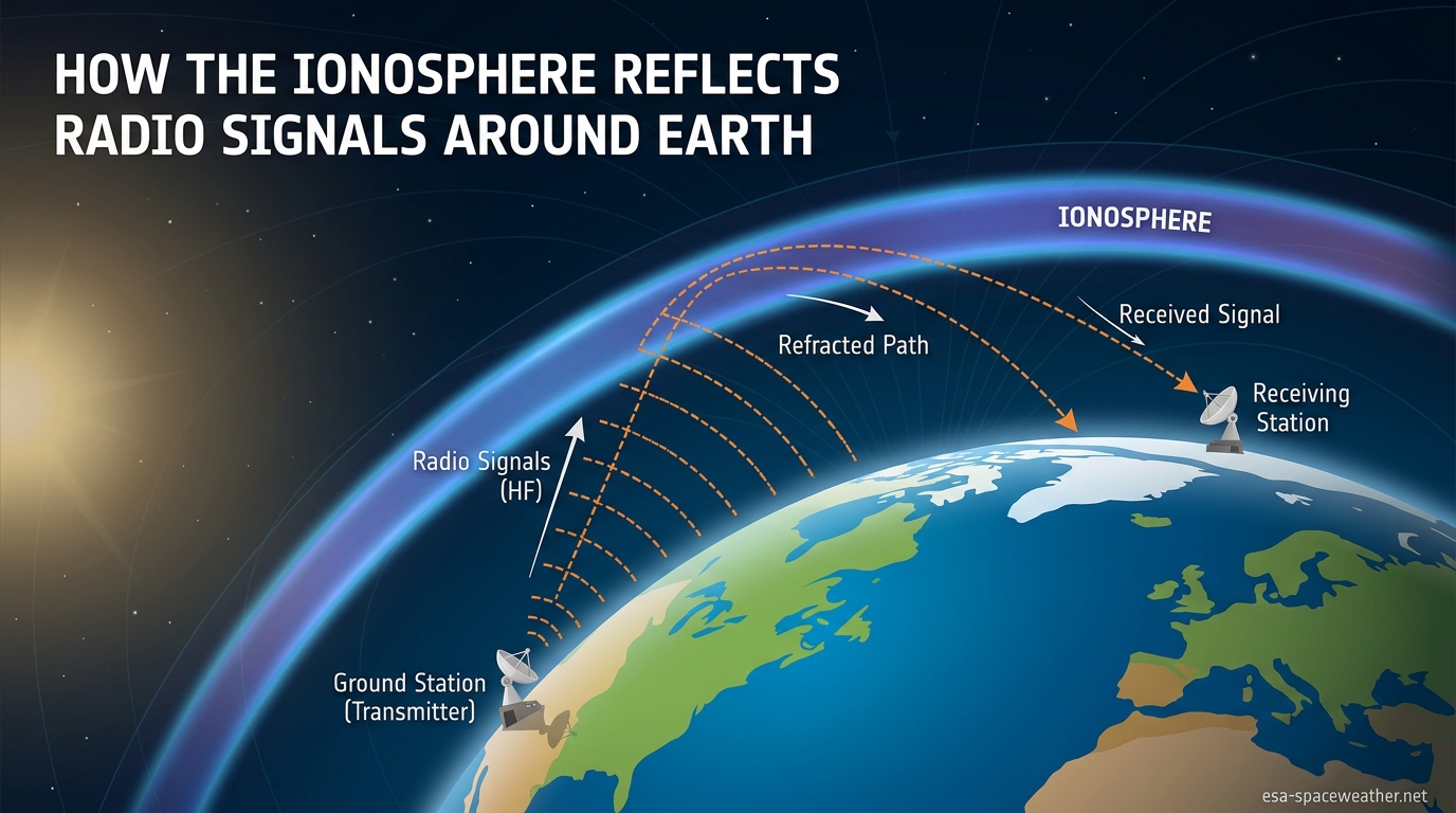
Long before satellites circled the globe and fiber-optic cables crisscrossed ocean floors, a single radio signal could travel from one side of the planet to the other. It did not rely on infrastructure or relays. Instead, it bounced off a charged layer of gas high above the Earth’s surface and came right back down, sometimes thousands of kilometers from where it started. That layer is the ionosphere, and the process is called skywave propagation.
Understanding how the ionosphere reflects radio signals around the curve of the Earth connects physics, atmospheric science, and practical radio engineering. It explains why ham radio operators in New York can chat with operators in Japan, why shortwave broadcasts from London reach listeners in Africa, and why a 100-watt transmitter can cover more distance than a 50,000-watt FM station. It also explains why those same signals vanish or distort when space weather turns violent.
In this guide, we break down the entire mechanism from the ground up. We cover what the ionosphere is made of, how free electrons interact with radio waves, why only certain frequencies bend back to Earth, and how multiple bounces let signals follow the planet’s curvature. We also connect the science to real-world uses, from emergency communication to international broadcasting, and tie it all to space weather conditions that our team monitors daily.
Table of Contents
Quick Answer: How the Ionosphere Reflects Radio Signals Around the Curve of the Earth
The ionosphere reflects radio signals through a process better described as gradual refraction. High-frequency (HF) radio waves between roughly 3 and 30 MHz travel upward from a transmitter and enter the ionized upper atmosphere. There, free electrons set in motion by solar ultraviolet radiation cause the waves to bend. As the electron density increases with altitude, the bending becomes sharper until the wave reverses direction and heads back toward the ground. When it strikes the Earth’s surface, it reflects back up and repeats the process. This bouncing, known as multi-hop propagation, is how the ionosphere reflects radio signals around the curve of the Earth without any physical mirror.
What Is the Ionosphere?
The ionosphere is a region of Earth’s upper atmosphere where solar radiation strips electrons from gas atoms and molecules, creating a layer of plasma. It sits roughly 50 to 600 kilometers (30 to 370 miles) above the surface, overlapping parts of the mesosphere, thermosphere, and exosphere. Unlike the dense air we breathe at ground level, the ionosphere is incredibly thin. But what it lacks in density, it makes up for in electrical charge.
Ultraviolet light, extreme ultraviolet (EUV), and X-ray photons from the Sun slam into neutral atoms and molecules in this region. Each collision knocks an electron loose, leaving behind a positively charged ion. The freed electrons are what matter for radio communication. They oscillate in response to passing electromagnetic waves and, in sufficient numbers, bend those waves back toward Earth.
This ionization process is not constant. It intensifies during daylight hours when solar radiation floods the upper atmosphere and weakens at night when recombination outpaces ionization. Solar flares, coronal mass ejections, and the 11-year sunspot cycle all change how many free electrons are available. That variability is why radio propagation conditions shift from hour to hour, day to day, and season to season.
The ionosphere is not a single uniform shell. It has distinct sub-layers, each at a different altitude with different properties and different effects on radio waves. We will explore those layers in detail shortly, but the key takeaway is that the ionosphere behaves like a dynamic, electrically charged ocean hovering above our heads.
How the Ionosphere Reflects Radio Signals Around the Curve of the Earth: The Refraction Mechanism
Strictly speaking, the ionosphere does not reflect radio waves the way a bathroom mirror reflects light. The correct physical term is refraction, which means the wave gradually bends as it passes through a medium with changing properties. But for radio operators and in common usage, “reflection” is the accepted shorthand because the end result is the same: the signal comes back down.
Here is the step-by-step mechanism. A transmitter on the ground sends an HF radio wave upward at an angle. As the wave climbs into the ionosphere, it encounters regions of increasing electron density. Free electrons in the plasma respond to the wave’s electromagnetic field by oscillating. That oscillation slows the wave’s phase velocity. The change in speed causes the wave front to tilt, just like a car whose left wheels hit a patch of ice while the right wheels stay on dry pavement. The car veers. The radio wave bends.
The deeper the wave penetrates into the ionosphere, the denser the electron population becomes, and the more the wave bends. If conditions are right, the bending is sharp enough to send the wave back toward the ground. It exits the ionosphere at an angle roughly matching its entry, traveling downward until it reaches the surface hundreds or thousands of kilometers away.
This is a critical point that many sources gloss over: the wave does not hit a hard boundary and bounce. It curves. Think of a skateboarder entering a half-pipe. The ramp is smooth and continuous, but the curvature redirects the skater from downward to upward without any wall or impact. The ionosphere does the same thing to radio waves, except it redirects them from upward to downward.
The reason this matters for global communication is geometry. Earth is curved, so line-of-sight radio signals cannot follow the surface beyond about 40 to 50 kilometers for typical antenna heights. But a signal that goes up, bends in the ionosphere, and comes back down can land on the far side of that curvature. With enough hops, it can reach the other side of the planet.
Refraction vs. Reflection: Why the Distinction Matters
Experienced ham radio operators on forums like Reddit’s r/amateurradio frequently point out that calling the process “reflection” is technically inaccurate. They are right. True reflection occurs at a boundary where a wave cannot penetrate, like light hitting a metal surface. Refraction occurs within a medium where properties change gradually. The ionosphere does the latter.
That said, the practical difference is minimal for most users. Radio operators plan their contacts using the same angles, distances, and frequency rules regardless of whether they say “bounce” or “bend.” What matters is understanding that the bending depends on electron density, wave frequency, and angle of incidence. Change any of those three variables and the signal behaves differently.
The Ionospheric Layers: D, E, and F
The ionosphere is divided into four main layers based on altitude and electron density. Each one interacts with radio waves differently. Some bend signals back to Earth, some absorb them, and some vanish entirely at night. Understanding these layers is essential for predicting propagation conditions.
The D Layer (60 to 90 km)
The D layer is the lowest ionospheric layer, sitting between 60 and 90 kilometers above the surface. It forms during daylight hours when solar radiation ionizes nitrogen and oxygen molecules at that altitude. Electron density here is lower than in higher layers, but the air is still relatively dense. That means free electrons collide frequently with neutral molecules, absorbing energy from passing radio waves rather than bending them.
The D layer is the enemy of daytime HF communication on lower frequencies. Signals in the 3 to 10 MHz range that pass through it lose significant energy. This is why shortwave listeners often report that distant AM stations fade during the day but roar back to life after sunset. At night, the D layer disappears because recombination takes over without sunlight to sustain ionization. HF signals pass through freely and reach the higher reflecting layers unimpeded.
The E Layer (90 to 150 km)
The E layer sits above the D layer, between 90 and 150 kilometers in altitude. It has moderate electron density and can reflect radio signals in the lower HF range, particularly below about 5 MHz during the day. The E layer is predictable and relatively stable compared to other ionospheric regions.
Under normal conditions, the E layer provides reliable short-distance skywave propagation. But it also hosts an interesting phenomenon called sporadic E, where dense patches of ionization appear unpredictably. Sporadic E can reflect much higher frequencies, sometimes including VHF signals above 30 MHz. Ham radio operators and FM listeners have reported receiving signals from 1,000 or more kilometers away during summer sporadic E events, a phenomenon that feels almost magical to those who experience it.
The F Layer (150 to 600 km)
The F layer is where the heavy lifting happens for long-distance HF communication. During daylight hours, it splits into two sub-layers: F1 (roughly 150 to 220 km) and F2 (roughly 220 to 600 km). At night, these merge into a single F layer.
The F2 layer is the most important region for skywave propagation. It has the highest electron density of any ionospheric layer, which means it can reflect the highest frequencies. During periods of high solar activity, the F2 layer can bend signals at 30 MHz or even higher back to Earth. This layer persists day and night, though its density drops significantly after sunset. It is responsible for the majority of intercontinental HF contacts made by amateur radio operators and shortwave broadcasters.
The altitude of the F2 layer also matters. Because it sits so high, a single reflection from F2 covers a large distance. Signals bouncing off the F2 layer at a low angle can land 3,000 to 4,000 kilometers from the transmitter in a single hop. That is roughly the distance from New York to London in one bounce.
Skywave Propagation and Multi-Hop: How Signals Curve Around the Planet
A single hop off the ionosphere can carry a signal thousands of kilometers, but it cannot reach the opposite side of the Earth. For truly global communication, the signal needs to bounce multiple times. This process is called multi-hop propagation, and it is the mechanism by which the ionosphere reflects radio signals around the curve of the Earth.
The cycle works like this. A transmitter sends an HF signal upward at a shallow angle. The wave enters the ionosphere, refracts, and comes back down to Earth hundreds or thousands of kilometers away. When it hits the ground, the Earth’s surface acts as a reflector, particularly if the terrain is water or relatively flat land. The signal bounces back up into the ionosphere for another round of refraction. Each up-and-down cycle is called a hop.
Each hop incurs losses. The signal loses energy passing through the D layer twice per hop (during the day), loses energy reflecting off the ground, and loses energy to geometric spreading. After two or three hops, the signal is substantially weaker. But with a powerful enough transmitter and a sensitive enough receiver, contacts at 15,000 to 20,000 kilometers are achievable.
The distance covered in a single hop depends on the angle at which the signal hits the ionosphere. A signal sent nearly straight up covers a short distance. A signal sent at a very shallow angle, nearly parallel to the ground, covers the maximum distance per hop. Operators call this low-angle radiation, and it is why directional antennas for long-distance work are designed to concentrate energy close to the horizon.
Skip Distance and the Skip Zone
One of the most confusing aspects of skywave propagation for beginners is the skip zone. When a signal goes up and comes back down far away, there is a region between the maximum ground-wave range and the point where the skywave first touches down where no signal is received. This dead zone is called the skip zone.
Skip distance is the minimum distance from the transmitter at which the skywave returns to Earth. It depends on frequency, ionospheric conditions, and the angle of radiation. Higher frequencies and lower radiation angles generally produce longer skip distances. Operators trying to contact stations within their skip zone cannot do so using normal skywave propagation. This is where NVIS becomes valuable.
NVIS: Near Vertical Incidence Skywave
NVIS is a specialized propagation mode where the signal is sent almost straight up into the ionosphere and comes back down in a circular pattern covering roughly 300 to 500 kilometers. It fills the skip zone that normal skywave propagation creates.
Emergency communication teams rely heavily on NVIS because it provides statewide or regional coverage without requiring repeaters, satellites, or tall towers. A simple dipole antenna installed close to the ground can radiate energy nearly straight up, and the F layer reflects it back over a broad area. During disasters when cell towers and internet infrastructure are down, NVIS is often the only way to maintain communication within a disaster zone.
The HF Sweet Spot: Why Only Some Frequencies Bounce Back
The ionosphere does not reflect all radio frequencies. It acts like a frequency-selective mirror that bends some signals back to Earth while letting others pass straight through into space. The key variable is the relationship between the signal’s frequency and the electron density of the ionosphere.
Every layer of the ionosphere has a critical frequency, defined as the highest frequency that will be returned to Earth when transmitted straight up. If the signal frequency exceeds the critical frequency for a given layer, the layer cannot bend it back and the wave passes through. The critical frequency depends on electron density and follows the formula fc = 9 times the square root of N, where N is the electron density in electrons per cubic centimeter.
For signals sent at an angle rather than straight up, the situation changes. Angled signals can use frequencies higher than the critical frequency and still be returned to Earth. The highest frequency that can be used for communication over a specific path is called the maximum usable frequency, or MUF. The MUF typically runs about three times the critical frequency for typical long-distance paths.
This is why the HF band, ranging from 3 to 30 MHz, is the sweet spot for skywave propagation. Frequencies below 3 MHz (the MF and LF bands) suffer heavy absorption in the D layer during daytime. Frequencies above 30 MHz (the VHF and UHF bands) generally exceed the ionosphere’s critical frequency and punch straight through into space. Only within the HF range do the conditions consistently align to bend signals back to Earth.
Radio operators constantly adjust their working frequency based on current conditions. During the day, when the D layer absorbs lower frequencies, operators move higher in the HF band, often working between 14 and 28 MHz. At night, when the D layer disappears, they shift down to the 3 to 7 MHz range where signals can reach distant stations that were unreachable during daylight.
Why FM Radio and TV Signals Do Not Bounce
A common question from beginners is why FM radio (88 to 108 MHz) and television signals do not reflect off the ionosphere the way shortwave does. The answer is simple: those frequencies far exceed the ionosphere’s critical frequency. The electron density in even the strongest F2 layer is insufficient to bend signals at 100 MHz. They penetrate the ionosphere and continue into space, which is why FM stations are limited to line-of-sight reception of roughly 50 to 100 kilometers.
The rare exception is sporadic E propagation, which can create dense enough ionization patches in the E layer to reflect VHF signals. When this happens, listeners may briefly receive FM stations from hundreds of kilometers away. But sporadic E is unpredictable and short-lived, typically lasting minutes to a few hours.
How Solar Activity and Space Weather Affect Ionospheric Reflection
The ionosphere is entirely solar-powered. Every free electron that bends a radio wave exists because sunlight knocked it loose from an atom. This means the ionosphere is directly tied to solar activity, and changes on the Sun produce immediate effects on radio propagation here on Earth.
Solar activity follows an approximately 11-year cycle called the sunspot cycle. During solar maximum, the Sun produces more ultraviolet and EUV radiation, which creates higher electron densities in the ionosphere. Higher electron density means higher critical frequencies and higher MUFs. During solar maximum, operators routinely make contacts on the 10-meter band (28 MHz) that would be impossible during solar minimum. During solar minimum, the MUF drops and higher HF frequencies become unusable for skywave.
Solar Flares and Sudden Ionospheric Disturbances
Solar flares produce intense bursts of X-ray radiation that reach Earth in about eight minutes. When X-rays hit the dayside ionosphere, they dramatically increase ionization in the D layer. This causes a sudden ionospheric disturbance, or SID, which can absorb HF signals completely on the sunlit side of the planet for minutes to hours. Operators call this a shortwave fadeout, and it can wipe out all HF communication with no warning.
Geomagnetic Storms and Ionospheric Storms
Coronal mass ejections, or CMEs, send clouds of charged particles toward Earth. When these particles arrive one to three days after the eruption, they interact with the magnetosphere and trigger geomagnetic storms. These storms disturb the ionosphere, causing what are called ionospheric storms.
During an ionospheric storm, the F2 layer can become depleted of electrons, reducing the MUF and shortening maximum communication distances. Signals may fade, shift in frequency due to Doppler-like effects, or disappear entirely. Aurora also intensifies during geomagnetic storms, and the charged particles that create auroral displays can absorb HF signals passing through high-latitude regions. This is known as auroral absorption and it creates a communications blackout zone around the polar regions.
For anyone involved in radio communication, monitoring space weather is as important as checking the local forecast. NOAA’s Space Weather Prediction Center provides real-time data on solar flux, geomagnetic conditions, and ionospheric parameters. Ham radio operators check these reports before attempting long-distance contacts, just as sailors check marine forecasts before heading out.
Practical Applications of Ionospheric Radio Propagation
The ability to bounce signals off the ionosphere has shaped global communication for over a century. Even in the satellite era, skywave propagation remains actively used across multiple fields.
Shortwave broadcasting: International broadcasters like the BBC World Service, Voice of America, and Radio Romania International still transmit on shortwave frequencies to reach listeners across continents. A single transmitter in Europe can reach audiences in Africa, the Middle East, and Asia without any local infrastructure on the receiving end.
Amateur radio: Ham radio operators are the most active users of skywave propagation today. With as little as 100 watts of power and a simple wire antenna, operators regularly make contacts spanning 10,000 kilometers or more. During special events and contests, thousands of operators worldwide participate in DXing, the pursuit of distant contacts, entirely dependent on ionospheric conditions.
Maritime and aviation communication: Ships at sea and aircraft on transoceanic routes have historically relied on HF skywave for long-range communication. While satellite systems have largely replaced HF for routine traffic, maritime and aviation HF frequencies remain active as backup systems. When satellites fail or are unavailable, ionospheric propagation is the fallback.
Emergency and disaster communication: When earthquakes, hurricanes, or other disasters destroy local communication infrastructure, amateur radio operators deploy with portable HF equipment to provide emergency communication. NVIS propagation is particularly valuable here, as it provides regional coverage without requiring repeaters or towers. Organizations like the Amateur Radio Emergency Service (ARES) and the Radio Amateur Civil Emergency Service (RACES) train specifically for these scenarios.
Military communication: Military forces worldwide maintain HF skywave communication systems as a resilient alternative to satellite-dependent networks. Over-the-horizon radar systems also use ionospheric reflection to detect aircraft and ships at ranges exceeding 3,000 kilometers, well beyond the line-of-sight limit of conventional radar.
Radio astronomy: NASA’s Radio Jove project uses ground-based radio telescopes to observe natural radio emissions from Jupiter and the Sun. These observations depend on understanding ionospheric conditions, since the ionosphere affects which frequencies can reach ground-based receivers from space. The same plasma physics that bend HF signals also filter which cosmic signals astronomers can detect from Earth’s surface.
A Brief History: From Marconi to the Kennelly-Heaviside Layer
The story of ionospheric reflection begins in 1901 when Guglielmo Marconi successfully transmitted a radio signal from Cornwall, England, to St. John’s, Newfoundland, a distance of about 3,500 kilometers. At the time, scientists believed radio waves traveled only in straight lines. Since the curvature of the Earth should have blocked any signal over that distance, Marconi’s success was a mystery.
In 1902, Oliver Heaviside in England and Arthur Kennelly in the United States independently proposed that a conducting layer in the upper atmosphere was reflecting radio waves back to Earth. This hypothetical layer became known as the Kennelly-Heaviside layer. It took another 24 years before Edward Appleton experimentally confirmed its existence in 1924, using techniques that earned him the Nobel Prize in Physics in 1947.
The term “ionosphere” was introduced by Robert Watson-Watt in 1926, and the layered structure (D, E, and F regions) was mapped out through the 1930s. The discovery transformed radio engineering. For the first time, operators understood why signals traveled the distances they did, and they could begin predicting and optimizing propagation conditions rather than relying on trial and error.
FAQs
What layer reflects radio waves around the Earth?
The F2 layer of the ionosphere, located roughly 220 to 600 kilometers above Earth’s surface, is the primary layer responsible for reflecting HF radio signals over long distances. It has the highest electron density of any ionospheric layer and persists day and night, making it the workhorse of intercontinental radio communication.
How do radio waves curve around the Earth?
Radio waves curve around the Earth through multi-hop propagation. A signal goes up to the ionosphere, bends back down to the surface, reflects off the ground, and repeats the cycle. Each hop covers hundreds to thousands of kilometers, and successive hops trace the planet’s curvature, enabling truly global communication.
How does sky wave propagation work?
Skywave propagation works when an HF radio signal (3 to 30 MHz) enters the ionosphere and is refracted by free electrons back toward Earth. The signal lands far from the transmitter, bounces off the ground, and repeats. This bouncing allows signals to travel far beyond the horizon without satellites.
What is the 3-3-3 rule for radios?
The 3-3-3 rule is a general emergency communication guideline suggesting that you should have three ways to communicate, be able to reach someone within three hours, and maintain contact for three days. It emphasizes redundancy in communication planning, including using HF radio as a backup when primary systems fail.
Are skywaves still used today?
Yes, skywaves are actively used today by amateur radio operators, shortwave broadcasters, maritime and aviation services, military communication networks, and emergency response teams. While satellites and internet-based systems handle most routine traffic, skywave propagation remains a critical backup and the only option in many remote or disaster scenarios.
Why can radio waves travel around the Earth but light cannot?
Radio waves in the HF range (3 to 30 MHz) have long enough wavelengths that they interact with free electrons in the ionosphere and are refracted back to Earth. Visible light and higher-frequency radio waves like FM and TV signals have shorter wavelengths that penetrate the ionosphere and continue into space. The ionosphere only bends frequencies below its critical frequency.
How does solar activity affect ionospheric reflection?
Solar activity directly controls ionospheric electron density. During solar maximum, higher radiation increases electron density, raises critical frequencies, and opens higher HF frequencies for skywave use. Solar flares cause sudden absorption blackouts, and geomagnetic storms from coronal mass ejections disrupt the F2 layer, reducing communication range and causing signal fading.
Conclusion
Understanding how the ionosphere reflects radio signals around the curve of the Earth reveals one of nature’s most useful phenomena. Solar radiation creates a charged layer of plasma in the upper atmosphere. Free electrons in that plasma refract HF radio waves back toward the ground. The signal bounces off the surface and repeats, tracing the planet’s curvature hop by hop until it reaches the other side of the world.
This process, called skywave propagation, is why a modest radio in your backyard can reach operators on distant continents. It is why shortwave broadcasting thrived for decades and why emergency communicators still train on HF frequencies today. And because the ionosphere is entirely solar-powered, every contact you make is a direct reflection of conditions on the Sun.
Whether you are a ham radio operator chasing distant contacts, a shortwave listener exploring international broadcasts, or simply curious about the physics of global communication, the ionosphere is the invisible mirror that makes it all possible. Monitoring space weather conditions helps you predict when that mirror will be clear, cloudy, or cracked, and that knowledge can make the difference between a successful contact and dead air.